By Nuvation | Jul 24, 2013
Here’s the conclusion of our Power Supply Design Basics series! First we introduced the concept of the Power Factor, and then we discussed Power Factor Correction (PFC) and how to implement passive PFC. Here we’ll delve into active PFC, and when you would want to use it.
For any power supply design over 100W, the preferable type of PFC is Active Power Factor Correction (Active PFC) since it provides a lighter and more efficient power factor control. Active PFC is comprised of a switching regulator operating at a high switching frequency, being able to generate a theoretical power factor of over 95%. Active Power Factor Correction automatically corrects for AC input voltage, and is capable of a wide range of input voltage. One disadvantage of Active PFC is the extra cost resulting from the additional complexity required in its implementation.
Active Power Correction Circuit
The diagram below depicts the basic elements of an active power factor correction circuit. The control circuit measures both the input voltage (pin 2 on the controller) as well as the current (RS and pins 3 and 11 on the controller) and adjusts the switching time and duty cycle to present an in phase voltage and current load to the input.
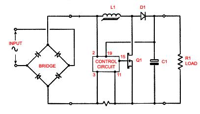
The active PFC shown above is in the form of a boost regulator and as a result the voltage appearing across the load (R1) must be greater than the highest value of the peak voltage appearing at the input. Normally, the DC voltage is set to 10 to 20V higher than the expected maximum peak input voltage. Designing a universal input power supply (87-266Vrms at 47-63Hz) the DC output voltage from the PFC at the input to the DC-DC converter would be set at 386V to 396V.
Using an active PFC circuit, any input voltage 87 266 V (RMS) can be accommodated and power factors 0.98 can be achieved with relative ease.
PFC Boost Regulator
Below is the basic block diagram of a PFC boost regulator. Unlike a standard power supply input there is no holdup capacitor directly across the bridge rectifier so that there is no large inrush current or transient currents as the input voltage rises above the voltage on the capacitor. The PFC works by inducing a current in the inductor (L1, See Figure 1 above) and causing the current to track the input voltage.
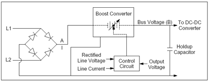
The control circuit senses both the input voltage and the current flowing through the circuit. By controlling the on time in the switch (Q1) that places L1 across the output of the rectifier, the current in the coil increases as the input voltage increases. The switch is turned off periodically and the voltage at the drain end rises until the current in the inductor achieves the charge level. Usually, this level is set to several volts higher than the bridge rectifier peak output voltage. A boost regulator’s output voltage must be higher than the input voltage for the regulator to function correctly.
The DC output voltage of the boost regulator is also sensed and the charge discharge cycle on the inductor is adjusted to maintain a constant output voltage. There is a requirement that the switching rate of the boost converter be much higher than the line frequency, typically these converters switch at rates of 20kHz to 100kHz. The higher frequency allows for a small inductor to be used. To compare, the inductor in the passive PFC described earlier needs to be in the range of 150mH – 300mH whereas the inductor required in the active PFC is in the order of 10µH – 30µH. The difference is a full four orders of magnitude. This allows the use of physically small and light low-loss parts.
Advantages and Disadvantages
Primary advantages of the Active PFC:
- Power factor ≥ 0.95
- Constant Intermediate voltage to drive the DC/DC converter, simplifies the requirements and the complexity of the DC/DC converter.
- Small, light inductive components.
- Wide range of input voltages, can work with 87Vrms – 266Vrms 47Hz-63Hz without switching
- Greater flexibility and control
The Primary disadvantages of the Active PFC are:
- Higher overall cost and complexity
- Requires better filtering to prevent high frequency hash from getting to the line
- Higher voltage components than would be required for a passive PFC